VMU hardware overview: Difference between revisions
Jump to navigation
Jump to search
(fleshed out clock, RAM, ROM, power source, timers, input) |
(Added a link to the manual) |
||
| Line 13: | Line 13: | ||
* '''Timer''': Base Timer (14-bit binary up counter), 2xTimer Circuits (16-bit timer/counter with pulse generator) | * '''Timer''': Base Timer (14-bit binary up counter), 2xTimer Circuits (16-bit timer/counter with pulse generator) | ||
* '''Serial Interface''': Dedicated Maple interface (VMU-to-Dreamcast) or Synchronous 8-bit serial interface with 2 transfer channels (VMU-to-VMU) | * '''Serial Interface''': Dedicated Maple interface (VMU-to-Dreamcast) or Synchronous 8-bit serial interface with 2 transfer channels (VMU-to-VMU) | ||
[[:File:Vmu_Manual.pdf|Instruction Manual]] | |||
Revision as of 22:35, 27 December 2022
- CPU: 8-bit Sanyo LC86K87
- Clock: 32.8KHz quartz oscillator or 879.2kHz RC oscillator when operating standalone or 6MHz CF oscillator when plugged into the controller
- RAM: 256 bytes for applications, 256 reserved for system BIOS, 512 bytes of additional WRAM
- ROM: 4KB OS/firmware functionality, 16KB system BIOS program area
- Flash: 128 KB (200 blocks) with 8-bit FAT filesystem
- Power source: Two CR2032 batteries with auto-off function and low-battery detection circuit
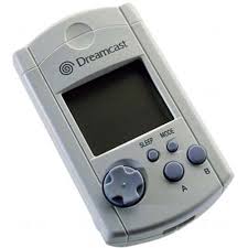
- Display: 48 dot Width x 32 dot Height resolution, Monochrome
- Display size: 37 mm (1.46 inches) Width x 26 mm (1.02 inches) Height
- Sound: PWM sound chip, 1-channel PWM sound source
- Input: 4-button D-pad, 2 general-purpose buttons (A, B), MODE, SLEEP
- Timer: Base Timer (14-bit binary up counter), 2xTimer Circuits (16-bit timer/counter with pulse generator)
- Serial Interface: Dedicated Maple interface (VMU-to-Dreamcast) or Synchronous 8-bit serial interface with 2 transfer channels (VMU-to-VMU)
