Maple bus
The Maple bus is the communications bus the Dreamcast uses to connect controllers and other related peripherals. It is a symmetrical serial protocol.
Hardware Overview
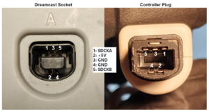
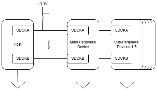
A Maple Bus consists of 2 signal/clock lines that are labeled SDCKA and SDCKB. Hardware on the Maple Bus consists of one host, zero or one main peripheral, and zero to five sub-peripherals. The only difference between a main peripheral and a sub-peripheral is that a main peripheral communicates to the host what sub-peripherals are attached during normal communication. The main peripheral is something like a Dreamcast controller, and the sub-peripherals are things like a VMU, jump pack, and microphone. The host and all connected peripheral devices communicate on the same 2-line Maple Bus. Devices are powered with 5V from the host, and signals on the Maple Bus operate at 3.3V TTL.
- Both lines on the Bus are pulled HIGH through weak pullup resistors
- Only one connected component on the bus may communicate at a time
- During communication, a device should not drive both lines HIGH for very long to prevent a downstream device from thinking the bus is free
- Before a component starts communicating, it must verify the bus is neutral for a sufficient amount of time
- A peripheral device will only communicate 1 packet of data in response to a request from the host
Maple Bus Signals
There is no handshaking done to determine how fast each component may transmit on the Maple Bus. Transmission speeds are internally pre-determined by each hardware component. Generally speaking, for all signals, the minimum amount of time between an edge (transition between logic levels) of one line and an edge of another is about 125 nanoseconds. The minimum amount of time between edges on the same line is about 225 nanoseconds. There is no maximum time limit as long as both lines aren't held HIGH during active transmission for any extended amount of time. These guidelines may be applied for any sequence below.
Start Sequence
Every packet begins with a start sequence.
- SDCKA is brought LOW
- SDCKB is toggled 4 times
- SDCKA is then brought back HIGH to complete the sequence
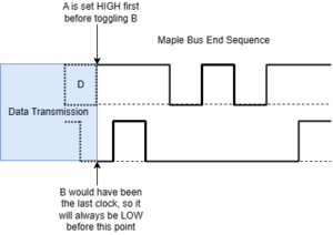
End Sequence
Every packet is completed with an end sequence to commit the data to the target component.
- SDCKA is brought HIGH
- SDCKB is toggled HIGH then LOW
- SDCKA is toggled 2 times
- SDCKB is brought back HIGH to complete the sequence
Data Bit Sequences
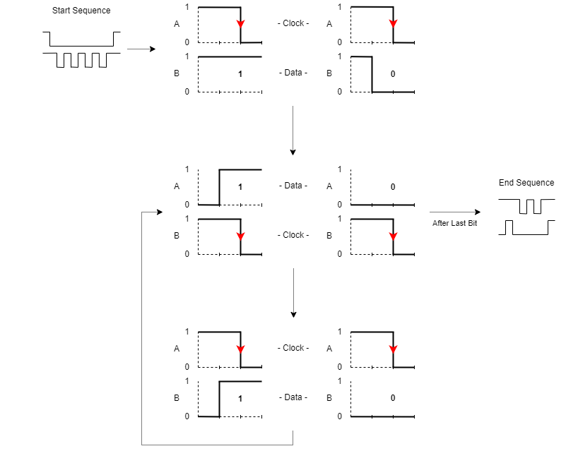
For each bit, one line of the maple bus acts as a clock while the other is the data to be sampled. A data bit is clocked when the designated clock line transitions from HIGH to LOW. The two lines trade their function after each bit. Line A acts as clock and B acts as data for the first bit. Line B acts as clock and A acts as data for the next bit. Line A acts as clock again for the bit after that. The pattern repeats until all data is transmitted.
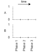
Each state transition can be broken down into 3 phases:
- Phase 1 - Clock Conditioning: Bring clock HIGH and keep data at the state it was previously
- Phase 2 - Data Conditioning: Transition the data bit to the target value
- Phase 3 - Clocking: Bring clock LOW in order to have the data bit sampled
There are a total of 6 types of state transitions, depending on what the previous phase was and the target bit value. A depiction of state transitions can be seen in the image below.
Notice that each line, A & B transitions states in a staggard pattern i.e., only one line may change its logic level within each phase. Because of the staggard pattern, the minimum time between an edge of one line and an edge of the other is 1 phase length, and the minimum time between edges on the same line is the sum of the time of 2 phases. The total bit transmission time is of course the sum of the time of all 3 phases.
- The Dreamcast host transmits each phase at about 160 nanoseconds
- This works out to be about 2 mbps data transfer speed
- Dreamcast controllers and other peripheral devices usually transmit a little slower at about 250 nanoseconds per phase and about 110 microsecond delays between each 3-word chunk after the first frame word
- This works out to between about 0.5 and 1.3 mbps data transfer speed
Maple Bus Packet
This section contains information about the packet structure inherent to the Maple Bus. Any data transmission follows this packet structure.
Word Format
Each word is 32 bits in length, transmitted in little-endian byte order. The most significant bit of each byte transmits first. This means that the most significant bit of the least significant byte of each word transmits first. All tables in this wiki list bytes in transmission order with the least significant bit (LSB) as the first byte.
When ASCII text or a byte stream is transmitted, the most significant byte is the first character of the 4 character sequence in each word. This means that the byte order of each word needs to be flipped before parsing the payload as a character or byte array. The size of an ASCII payload section is pre-determined based on the command. No NULL termination byte is supplied at the end of the string, and spaces (0x20) are used to pad out remaining characters at the end of the string.
Packet Data Format
A packet consists of the following data.
- Frame: 1 32-Bit Word
- Payload: 0 to 255 32-Bit Words
- CRC: 1 Byte
Frame Word
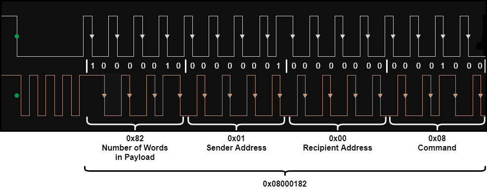
The following is how a frame word is broken down into its 4 parts.
| Byte 0 (LSB) | Byte 1 | Byte 2 | Byte 3 (MSB) |
|---|---|---|---|
Number of Words in Payload |
Sender Address |
Recipient Address |
Command
|
example:
Addressing
The following addresses are used for all components on the bus.
| Player Number | Host | Main Peripheral | Sub-Peripheral 1 | Sub-Peripheral 2 | Sub-Peripheral 3 | Sub-Peripheral 4 | Sub-Peripheral 5 |
|---|---|---|---|---|---|---|---|
| 1 | 0x00 | 0x20* | 0x01 | 0x02 | 0x04 | 0x08 | 0x10 |
| 2 | 0x40 | 0x60* | 0x41 | 0x42 | 0x44 | 0x48 | 0x50 |
| 3 | 0x80 | 0xA0* | 0x81 | 0x82 | 0x84 | 0x88 | 0x90 |
| 4 | 0xC0 | 0xE0* | 0xC1 | 0xC2 | 0xC4 | 0xC8 | 0xD0 |
*When the main peripheral responds with its sender address, it also sets the bits corresponding to which sub-peripherals are attached. For example, if sub-peripherals 1 and 2 are attached to player 1's main peripheral, the main peripheral will set its sender address to 0x23. This informs the host what else is attached. The host should still set the recipient address to 0x20 when sending data to this peripheral though.
In testing, there have been cases where a peripheral will respond with a source address as if it is player 1. As such, the host should ignore whatever the upper 2 bits that the device uses as its source address.
Commands
| Command Value | Description | Communication Direction | Number of Payload Words | Expected Response** |
|---|---|---|---|---|
| 0x01 | Device Info Request* | Host->Device | 0 | 0x05 |
| 0x02 | Extended Device Info Request | Host->Device | 0 | 0x06 |
| 0x03 | Reset | Host->Device | 0 | 0x07 |
| 0x04 | Shutdown | Host->Device | 0 | 0x07 |
| 0x05 | Device Info | Device->Host | 28 | - |
| 0x06 | Extended Device Info | Device->Host | 48 | - |
| 0x07 | Acknowledge | Device->Host | 0 | - |
| 0x08 | Data Transfer | Device->Host | 2..255 | - |
| 0x09 | Get Condition | Host->Device | 1 | 0x08 |
| 0x0A | Get Memory Information | Host->Device | 2 | 0x08 |
| 0x0B | Block Read | Host->Device | 2 | 0x08 |
| 0x0C | Block Write | Host->Device | 3..255 | 0x07 |
| 0x0D | Get Last Error | Host->Device | 2 | 0x07 |
| 0x0E | Set Condition | Host->Device | 2..255 | 0x07 |
| 0xFB | File Error | Device->Host | 0 | - |
| 0xFC | Request Resend | Device->Host | 0 | - |
| 0xFD | Unknown Command | Device->Host | 0 | - |
| 0xFE | Function Code Not Supported | Device->Host | 0 | - |
*Most peripheral devices won't respond to any other command until device info is requested for the device.
**This is the expected response when device didn't experience an error
Payload
The structure of a payload is structured based on the command used in the frame word.
Device Info Payload Structure (cmd 0x05)
| Word 0 | Words 1-3 | Word 4 | Words 5-11 | Words 12-26 | Word 27 |
|---|---|---|---|---|---|
| Supported function codes mask* | Function definitions for up to 3 devices** | MSB: Region code 2 least significant bytes: first two characters of description ASCII string*** |
The rest of the description ASCII string*** | Producer information ASCII string** | 2 most significant bytes: standby current consumption 2 least significant bytes: maximum current consumption |
*The supported function codes mask in device info responses will contain the bitmask for 1 or more devices ex: a VMU will have a mask of 0x0000000E for Timer, Screen, and Storage.
**The first word in this set is meant for the most significant bit that is set to 1 in the function codes word
***Refer to the [word format](#word-format) section about how to parse ASCII strings.
Extended Device Info Payload Structure (cmd 0x06)
| Word 0 | Words 1-3 | Word 4 | Words 5-11 | Words 12-26 | Word 27 | Words 28-47 |
|---|---|---|---|---|---|---|
| Supported function codes mask* | Function definitions for up to 3 devices** | MSB: Region code 2 least significant bytes: first two characters of description ASCII string*** |
The rest of the description ASCII string*** | Producer information ASCII string*** | 2 most significant bytes: standby current consumption 2 least significant bytes: maximum current consumption |
Version information and/or capabilities ASCII string*** |
*The supported function codes mask in device info responses will contain the bitmask for 1 or more devices ex: a VMU will have a mask of 0x0000000E for Timer, Screen, and Storage.
**The first word in this set is meant for the most significant bit that is set to 1 in the function codes word
***Refer to the [word format](#word-format) section about how to parse ASCII strings.
Data Transfer Payload Structure (cmd 0x08)
| Word 0 | Words 1..255 |
|---|---|
| Function code | Data - device dependent structure |
Get Condition Payload Structure (cmd 0x09)
| Word 0 |
|---|
| Function code |
Get Memory Information Payload Structure (cmd 0x0A)
| Word 0 | Word 1 |
|---|---|
| Function code | Location word |
Block Read Payload Structure (cmd 0x0B)
| Word 0 | Word 1 |
|---|---|
| Function code | Location word |
Block Write Payload Structure (cmd 0x0C)
| Word 0 | Word 1 | Words 2..255 |
|---|---|---|
| Function code | Location word | Data - device dependent structure |
Get Last Error Payload Structure (cmd 0x0D)
| Word 0 | Word 1 |
|---|---|
| Function code | Location word |
Set Condition Payload Structure (cmd 0x0E)
| Word 0 | Words 1..255 |
|---|---|
| Function code | Condition - device dependent structure |
Common Payload Word Types
The following word types are used in some of the above payload structures.
Function Codes
The below are function codes which are used to address functionality in some payloads.
| Code / Mask | Description |
|---|---|
| 0x00000001 | Controller |
| 0x00000002 | Storage |
| 0x00000004 | Screen |
| 0x00000008 | Timer |
| 0x00000010 | Audio Input |
| 0x00000020 | AR Gun |
| 0x00000040 | Keyboard |
| 0x00000080 | Gun |
| 0x00000100 | Vibration |
| 0x00000200 | Mouse |
Location Word
Below defines a location word which is used to address blocks of memory in some peripherals.
| Byte 0 (LSB) | Byte 1 | Byte 2 | Byte 3 (MSB) |
|---|---|---|---|
| Block LSB | Block MSB | Phase | Partition |
- Block: Memory block number index
- Phase: Sequence number
- Partition: Partition number (normally 0)
CRC
CRC byte transmits last, just before the end sequence is transmitted. It is the value after starting with 0 and applying XOR against each byte in the packet.
