Serial interface: Difference between revisions
Jump to navigation
Jump to search
(Created page with "The Dreamcast has a serial interface on the back of the console used for several peripherals and for console debugging. {{DCWiki:Stub}}") |
m (moved link to coder's cable to the top of the page) |
||
| (4 intermediate revisions by the same user not shown) | |||
| Line 1: | Line 1: | ||
The Dreamcast has a serial interface on the back of the console used for several peripherals and for console debugging. | The Dreamcast has a serial interface on the back of the console used for several peripherals and for console debugging. | ||
The serial interface is used by the [[Coder's_cable]]. | |||
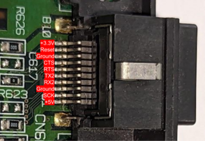
[[File:Serial Pinout.png|thumb|PCB Serial Port with Labeled Pins]] | |||
{| class="wikitable" | |||
|+Serial connector pinout | |||
|- | |||
! Pin | |||
! Description | |||
|- | |||
|1 | |||
| +5V | |||
|- | |||
|2 | |||
|SCK | |||
|- | |||
|3 | |||
|Ground | |||
|- | |||
|4 | |||
|RX2 | |||
|- | |||
|5 | |||
|TX2 | |||
|- | |||
|6 | |||
|RTS | |||
|- | |||
|7 | |||
|CTS | |||
|- | |||
|8 | |||
|Ground | |||
|- | |||
|9 | |||
|Reset | |||
|- | |||
|10 | |||
| +3.3V | |||
|} | |||
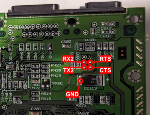
[[File:Serial Pads.png|thumb|Serial Connection Pinout for Test Points on Bottom of Board]] | |||
A SCIF loopback connection can be created to allow a Dreamcast to conduct and pass the SCIF test on the official Sega [[DC Checker]] diagnostics software by connecting pin 4 (RX2) to pin 5 (TXD) and connecting pin 6 (RTS) to pin 7 (CTS). | |||
{{DCWiki:Stub}} | {{DCWiki:Stub}} | ||
Latest revision as of 21:31, 3 July 2023
The Dreamcast has a serial interface on the back of the console used for several peripherals and for console debugging. The serial interface is used by the Coder's_cable.
| Pin | Description |
|---|---|
| 1 | +5V |
| 2 | SCK |
| 3 | Ground |
| 4 | RX2 |
| 5 | TX2 |
| 6 | RTS |
| 7 | CTS |
| 8 | Ground |
| 9 | Reset |
| 10 | +3.3V |
A SCIF loopback connection can be created to allow a Dreamcast to conduct and pass the SCIF test on the official Sega DC Checker diagnostics software by connecting pin 4 (RX2) to pin 5 (TXD) and connecting pin 6 (RTS) to pin 7 (CTS).
This page is a stub page. It needs to be expanded with more detail. If you know more information about this topic, please sign up and contribute to dreamcast.wiki!

